
This is a project I did a long time ago right after I finished my diploma in Electrical Engineering. We had built a step down transformer that would turn 220VAC into 1.5-24VAC during my vocational school time and I wanted to do something special with it. So this project was born.
We will talk about:
It's main features.
What's inside.
What's outside.
How it works.
It's circuitry.
You Are Welcomed to Watch This Video or Read This Blog Instead. I Think the Video Mentions More Than the Blog. So Maybe You Shouldn't Miss It!

1. It's main features are:
Doesn't have a microcontroller chip & most of the logic works with CD4000 series of logic chips.
It has an RF Remote Control for ease of use.
It has a wired keypad + Power terminal for ease of use.
It has 4 touch-sensitive keys on the body of the device.
It has four buttons that control everything on both the remote and the wired keypad and the body of the machine. Up, down, left and right.
It has an interface that uses LEDs to show graphics.
It Shows the input voltage, output voltage and output amps.
It has 3 fans (2 on the outside and one on the inside) to keep it cool.
It has overload protection made possible by a PTC, transistor and tungsten wire.
The logic control modules are powererd separately and control the power output.
It's input is designed to be 220VAC and the set output voltages are 1.5, 3, 4.5, 6, 7.5, 9, 12, 13.5, 18 & 24VAC. 3.2A @12V and 2A @24V.
In regulator mode, it's voltage selection is the following: 7.5, 9, 12, 13.5, 18, 24VDC x 0, 0.1, 0.2, ...., 0.8, 0.9, 1 = DC Output Voltage.
It can switch the power from DC to AC in an instant.
It can reverse the polarity in an instant.
The power can be disconnected without turning the unit off.
It has a beep function to inform user that the button has been pressed (can be turned off with a switch at the back).
It took me nearly a year to finish since I was new to digital circuitry and so there was much trial and error going on. But I managed to finish it and get it to a very well functioning order despite all of it's inefficiencies and engineering flaws (when I look back at it now).
I hope you can learn something from watching the video and reading this blog. Let's get to it!
2. What's Inside?
Less than a hundred transistors and about 20 CD4000 Logic ICs as well as a few small transformers to power up the logic boards. Yes one transformer is more than good enough to power up a logic board. However, I had completed this project with mostly salvaged parts from other devices. And it finally worked!

It looks like quite a mess on the inside and well to be honest it was never designed for mass production. It was mostly an educational project to myself. So any piece of kit that could do what I needed is put inside with a few wires soldered to it. Air flow is poor as well as I've tried to fit as many circuits as possible into that form factor. Sometimes forming the wires to make space for the kits was a challenge of its own!

Putting all the transformers together in the lower box was no small feat either. I had to fit the transformers for both powering up the logic boards and the output of the power supply. There had to be room to fit the LM350 regulator (it's a 3A adjustable regulator with short-circuit protection) with it's heatsink and cooling fan as well!

3. What's on the Outside?
A few touch buttons, Two rows of digital displays, An Antenna and a wired terminal with the 4 control buttons on it.


4. So How Does It Work?

You would need to hold your finger on the finger STANDBY touch button on the front (the small metal piece) or the RIGHT button on the side for 4 seconds to turn it on. Or to turn it off.

The selector switch is the single LED on top of the digits and other LEDs. You can move it to right and left using the RIGHT and LEFT arrow buttons. To make a change in the status of the chosen option, you can press UP. As simple as that. For some of the options such as choosing the output of the transformer or the percentage of output voltage of the LM350, you can press DOWN and it will function accordingly.

Positioning the LED on the Output Switch option for instance, will help you Open or Close the circuit you're powering.
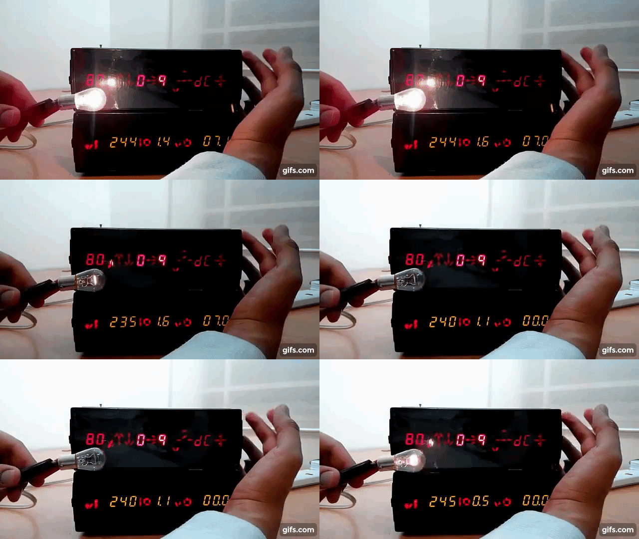
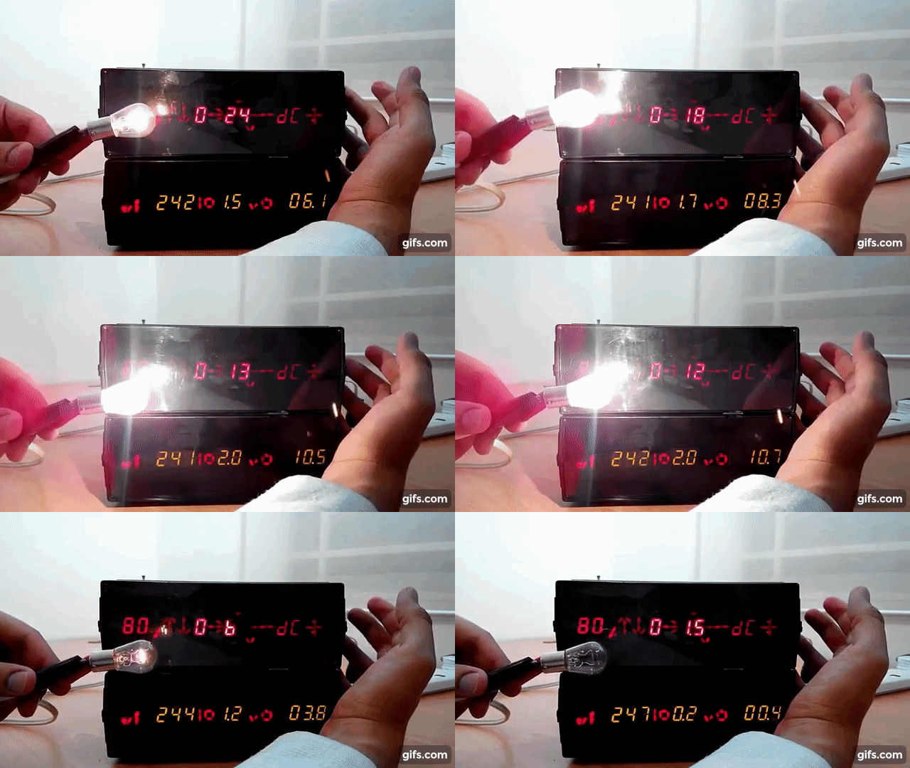
You can Select the output of the transformer through the UP and DOWN buttons on the body of the device. The light is the brightest at 13.5V because the transformer was designed to have the maximum power at that Voltage. I personally added the 18V and 24V outputs as well. Just so it has more outputs than the other transformers of my classmates :)
Manipulating the DC/AC option will turn the output into the AC version instantly! Here, we have two LEDs connected together in a Parallel connection and their polarities are against one another. They're both in series with a resistor to stop them from burning. You can clearly see that when the Power supply is on DC mode, only one of the LEDs is on. But when you switch to AC mode, both of them turn on because an AC voltage's polarity is constantly changing.
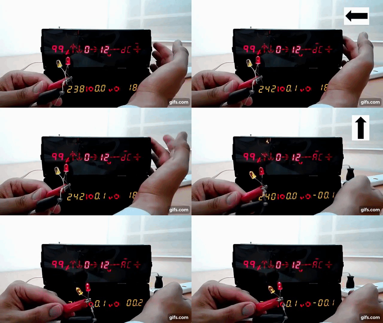
It's easy to change the polarity as well regardless of the AC/DC mode. It will just reverse the output. Here, we can see the same two LEDs taking turn and blinking because the polarity is being reversed:
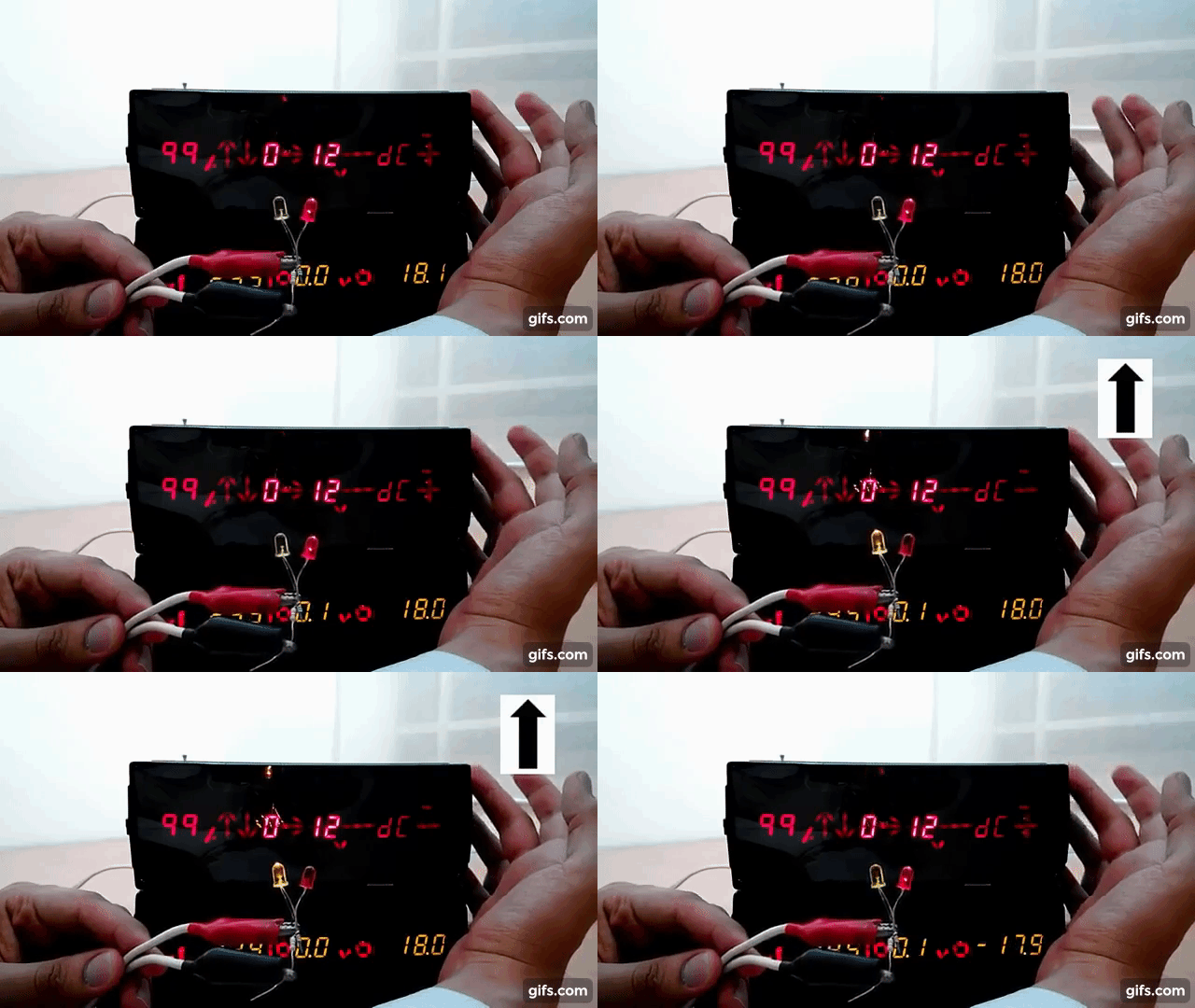
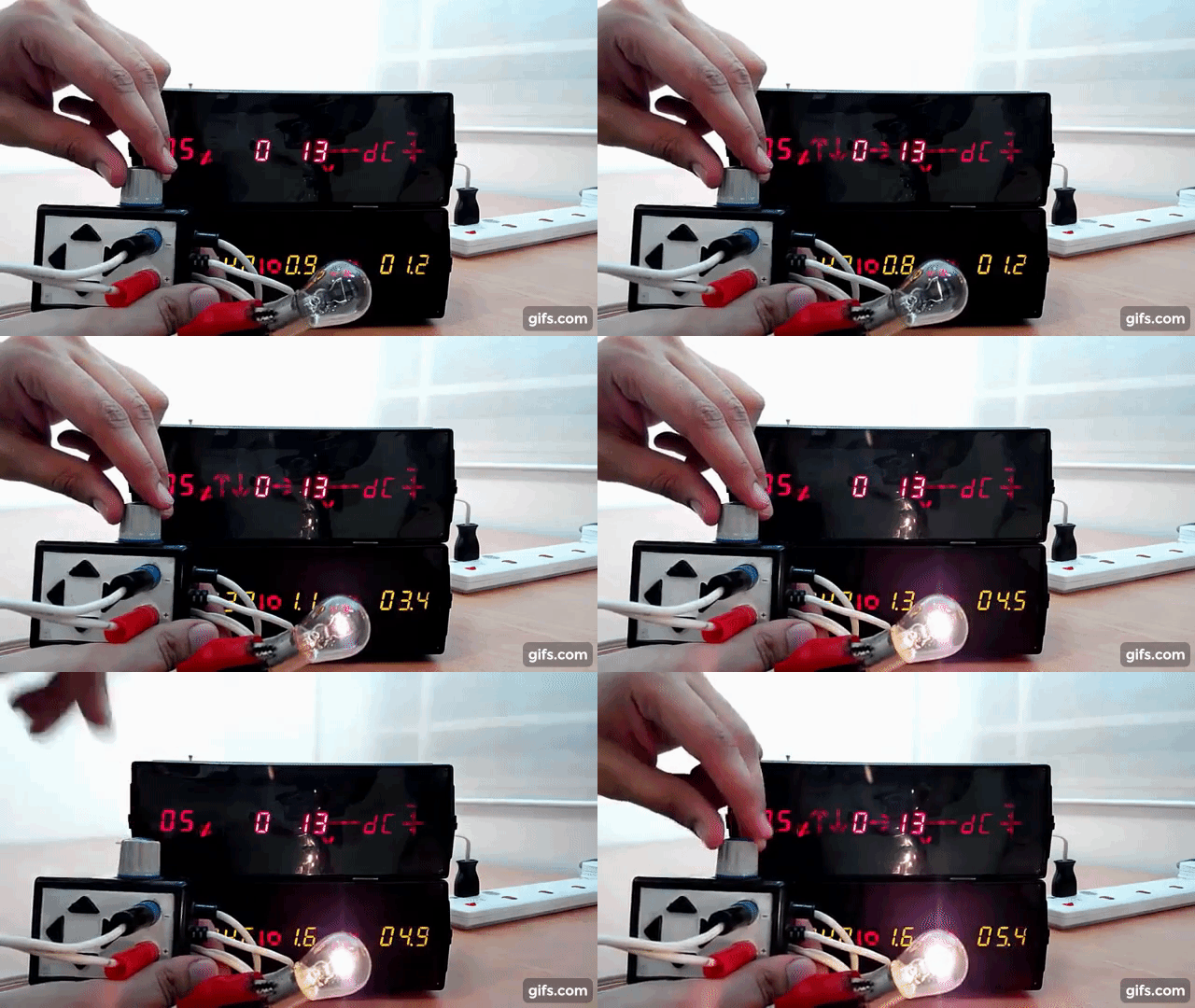
If you wish to have a Variable output voltage that is not within the set voltages of the transformer, you can activate the Regulator mode by positioning the LED on the RIGHT ARROW sign and pressing up. Then the percentage of the output voltage can be selected with via the UP/DOWN ARROWs or the volume knob on the wired terminal. If the wired terminal is connected, then the power supply will automatically choose the potentiometer over the Digital to Analog converter (regulator percentage) for voltage adjustments:
Any Safety Features?
Sure! This power supply is protected for short circuits on both the Variable Voltage (Regulator) mode and Fixed voltage mode.
On the Regulator mode, it's protected by the short circuit protection feature of the LM350. And on the fixed voltage mode, it's protected by a Thermal switch that is connected to the output in series. Both the input voltage (220VAC) as well as the terminals are fused as well!
The LM350 short circuit protection is able to protect the IC from burning very quickly. This IC is rated at 3A and whenever the output current usage would spike, it'll automatically cut the circuit. This IC is thermally protected as well by it's own internal sensors and circuitry.
The Thermal switch mentioned above has a very simple method of functioning. It is basically a low resistance (below 0.5 ohms) coil that can handle currents up to 3A without getting very hot. A PTC that is connected to a transistor is located in the middle of that coil. So anything above 3A will heat it up the coil enough to trigger transistor that is reading the PTC. The triggering action happens due to existence of a zener diode. I had to do a few trials to figure out the right voltages so then I can choose the right zener, (without calculation) but eventually I got it working.
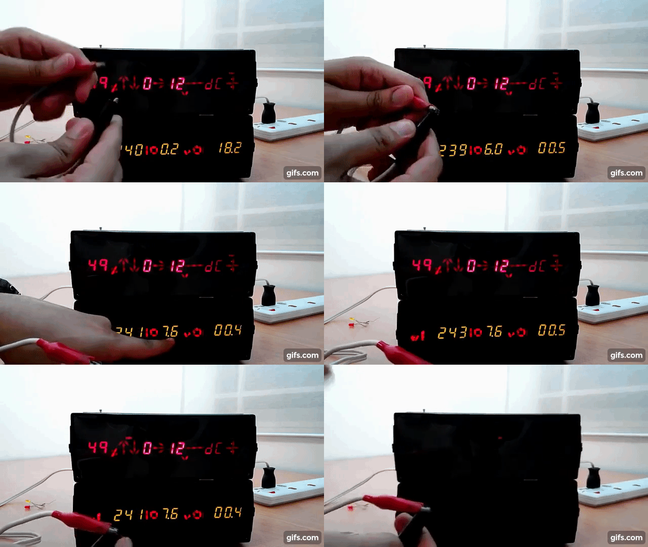
Below, we can see the Power Supply automatically shutting off itself after a short circuit on a fixed voltage. This Thermal Switch works well when the power supply has been under too much pressure as well. In function, It is similar to Motor Protection switches used for protecting 3-phase electric motors.

4. So What's the Circuitry?
Since the circuitry would be quite complicated to explain a text blog, I would recommend you to have a look at the video. In this part of the video I explain the circuitry in full detail along with very good examples and simulation. I hope you'd enjoy it!
Last words!
Although this project took me a year to finish and did manage to frustrate me more than a couple of times, I never regretted it. With all of it's flaws, I'm still proud of it since it became a reminder for my own capabilities. I did learn a lot when doing this project and it helped develop the foundation for digital electronics in my mind.
Long story short, I believe this is how we should learn electronics! Through projects. projects and more projects.
See you in the next one!

Comentários